Cicsco CCNA1 - Chapter 8 - некоторые выдержки
Некоторые выдержки из курса CCNA1 - chapter 8
Data transfer can be measured in three ways:
- Bandwidth - Throughput - Goodput Bandwidth
The capacity of a medium to carry data is described as the raw data bandwidth of the media. Digital bandwidth measures the amount of information that can flow from one place to another in a given amount of time.
Throughput is the measure of the transfer of bits across the media over a given period of time.
Goodput is the measure of usable data transferred over a given period of time, and is therefore the measure that is of most interest to network users.
Cable types with shielding or twisting of the pairs of wires are designed to minimize signal degradation due to electronic noise.
Optical fiber media implementation issues include:
More expensive (usually) than copper media over the same distance (but for a higher capacity)Different skills and equipment required to terminate and splice the cable infrastructure
More careful handling than copper media

Fiber Media
Generating and Detecting the Optical Signal
Either lasers or light emitting diodes (LEDs) generate the light pulses that are used to represent the transmitted data as bits on the media. Electronic semi-conductor devices called photodiodes detect the light pulses and convert them to voltages that can then be reconstructed into data frames.
Note: The laser light transmitted over fiber-optic cabling can damage the human eye. Care must be taken to avoid looking into the end of an active optical fiber.
Single-mode and Multimode Fiber
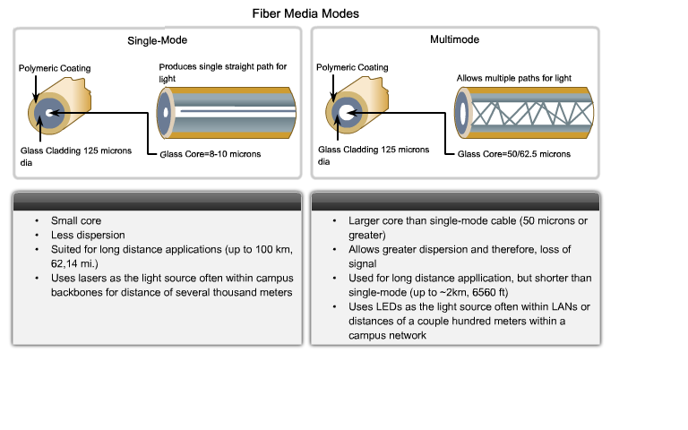
Fiber optic cables can be broadly classified into two types: single-mode and multimode.
Single-mode optical fiber carries a single ray of light, usually emitted from a laser. Because the laser light is uni-directional and travels down the center of the fiber, this type of fiber can transmit optical pulses for very long distances.
Multimode fiber typically uses LED emitters that do not create a single coherent light wave. Instead, light from an LED enters the multimode fiber at different angles. Because light entering the fiber at different angles takes different amounts of time to travel down the fiber, long fiber runs may result in the pulses becoming blurred on reception at the receiving end. This effect, known as modal dispersion, limits the length of multimode fiber segments.
Multimode fiber, and the LED light source used with it, are cheaper than single-mode fiber and its laser-based emitter technology.

Standard IEEE 802.11 - Commonly referred to as Wi-Fi, is a Wireless LAN (WLAN) technology that uses a contention or non-deterministic system with a Carrier Sense Multiple Access/Collision Avoidance (CSMA/CA) media access process.
Standard IEEE 802.15 - Wireless Personal Area Network (WPAN) standard, commonly known as "Bluetooth", uses a device pairing process to communicate over distances from 1 to 100 meters.
Standard IEEE 802.16 - Commonly known as Worldwide Interoperability for Microwave Access (WiMAX), uses a point-to-multipoint topology to provide wireless broadband access.
Global System for Mobile Communications (GSM) - Includes Physical layer specifications that enable the implementation of the Layer 2 General Packet Radio Service (GPRS) protocol to provide data transfer over mobile cellular telephony networks.
Common Optical Fiber Connectors
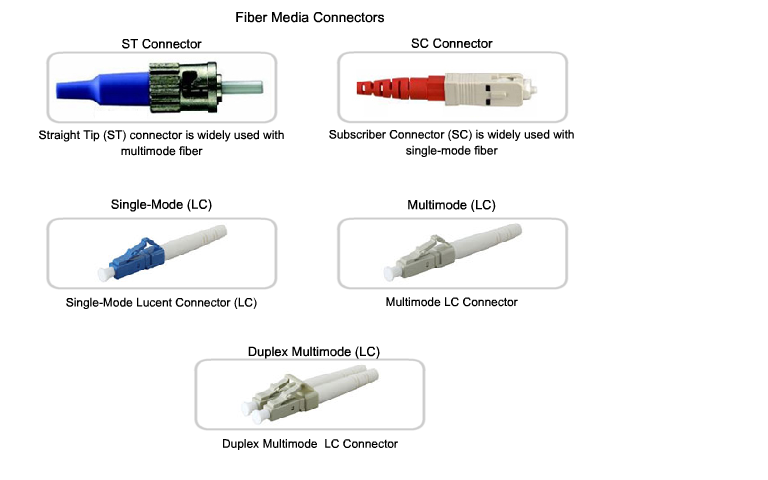
Fiber-optic connectors come in a variety of types. The figure shows some of the most common:
Straight-Tip (ST) (trademarked by AT&T) - a very common bayonet style connector widely used with multimode fiber.
Subscriber Connector (SC) - a connector that uses a push-pull mechanism to ensure positive insertion. This connector type is widely used with single-mode fiber.
Lucent Connector (LC) - A small connector becoming popular for use with single-mode fiber and also supports multi-mode fiber.

Terminating and splicing fiber-optic cabling requires special training and equipment. Incorrect termination of fiber optic media will result in diminished signaling distances or complete transmission failure.
Common Optical Fiber Connectors
Fiber-optic connectors come in a variety of types. The figure shows some of the most common:
Straight-Tip (ST) (trademarked by AT&T) - a very common bayonet style connector widely used with multimode fiber.
Subscriber Connector (SC) - a connector that uses a push-pull mechanism to ensure positive insertion. This connector type is widely used with single-mode fiber.
Lucent Connector (LC) - A small connector becoming popular for use with single-mode fiber and also supports multi-mode fiber.
Terminating and splicing fiber-optic cabling requires special training and equipment. Incorrect termination of fiber optic media will result in diminished signaling distances or complete transmission failure.
Three common types of fiber-optic termination and splicing errors are: Misalignment - the fiber-optic media are not precisely aligned to one another when joined.
End gap - the media do not completely touch at the splice or connection. End finish - the media ends are not well polished or dirt is present at the termination.
It is recommended that an Optical Time Domain Reflectometer (OTDR) be used to test each fiber-optic cable segment. This device injects a test pulse of light into the cable and measures back scatter and reflection of light detected as a function of time. The OTDR will calculate the approximate distance at which these faults are detected along the length of the cable.
A field test can be performed by shining a bright flashlight into one end of the fiber while observing the other end of the fiber. If light is visible, then the fiber is capable of passing light. Although this does not ensure the performance of the fiber, it is a quick and inexpensive way to find a broken fiber.
Размещено в разделе Cisco
24.10.2009
Комментарии:
Нет записей, оставьте свой комментарий.